INYO CONSTRUCTION NOTES
I constructed the Inyo as close to design dimensions specifications as I could and used electrical components as recommended. One of the analytical tools provided by Brett Nordgren is an Excel spreadsheet (Loop 8.xls) intended to model the performance of a force balance seismometer by analyzing the feedback loop. With this spreadsheet, a seismometer builder can quantitatively model the effect that critical mechanical and electrical components values have on performance. I ran this model many times with different mechanical weights and resistor and capacitor values to assess how these values changed the seismometer response. I satisfied myself that the design performance was hardly affected when reasonable tolerances were held.
This class of instrument consists of five major components: the base with component supports and leveling screws; a boom hinged at one end and counterbalanced by a spring; a capacitance sensor at the free end of the boom; a coil and magnet; and the force feedback electronics board.
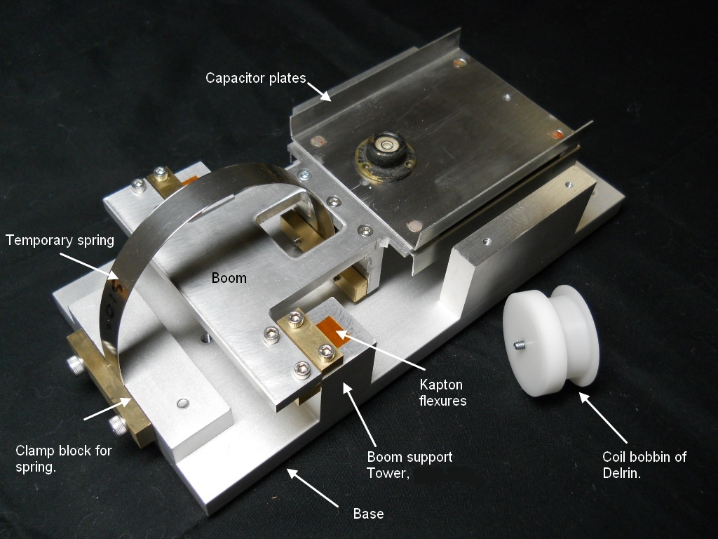
BASE AND BOOM
The photo above shows the main metal components of the seismometer. The base, support towers, and clamps are simple rectangular shapes easily created on a mill. The plans call for a boom using two pieces. I modified my construction of the boom combining booms 1 and 2 from a single piece of ¼" aluminum plate. The fabrication of the boom can be done by hand but is much easier using a milling machine. The capacitor plates are attached with soft, flush head aluminum rivets bucked with an arbor press. The coil bobbin or spool was turned from a rod of Delrin, wire has not yet been wound on it. The material for the thin flexures has evolved over the last few years with 0.003" Kapton (amber film in photo) being considered the most favorable.
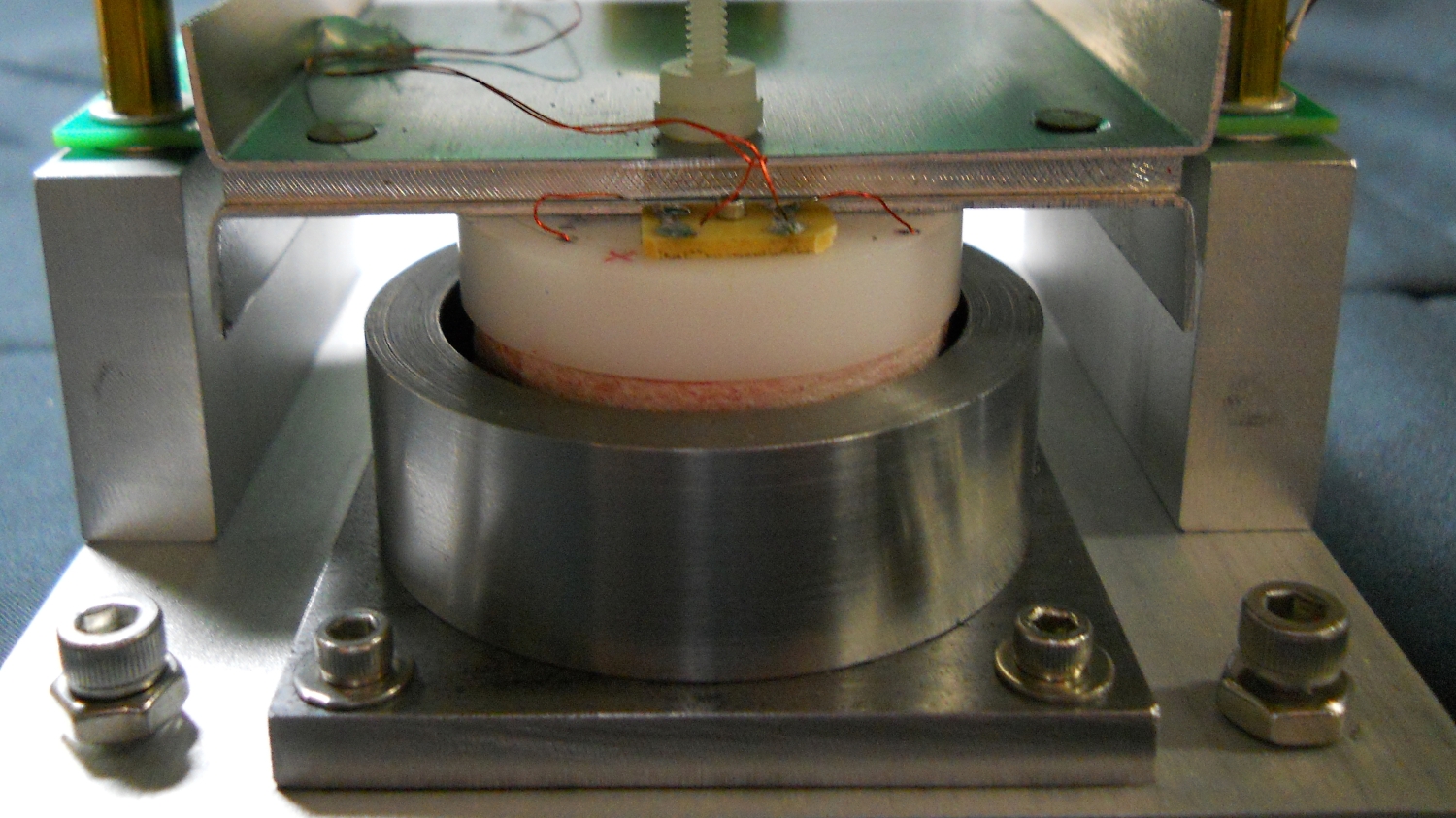
The magnet assembly consists of a mild steel base and 12L14 ring surrounding a strong neodymium magnet and steel cap. This assembly acts to concentrate the magnetic lines of force through the windings of the forcing coil. I made some modifications to this assembly, primarily by drilling a 1/2 inch hole in the base to access the screw that holds the magnet and cap together. Additionally I enlargened the holes for the four corner screws to allow room for adjustment so as to to accurately center the coil within the assembly.
MAGNET ASSEMBLY AND COIL
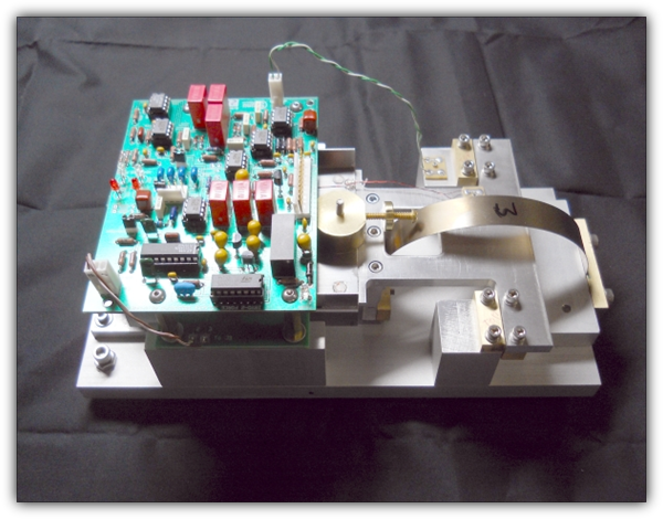
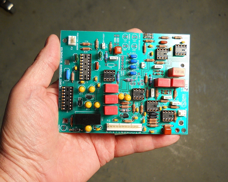
ELECTRONICS BOARD
CAPACITANCE SENSOR ASSEMBLY
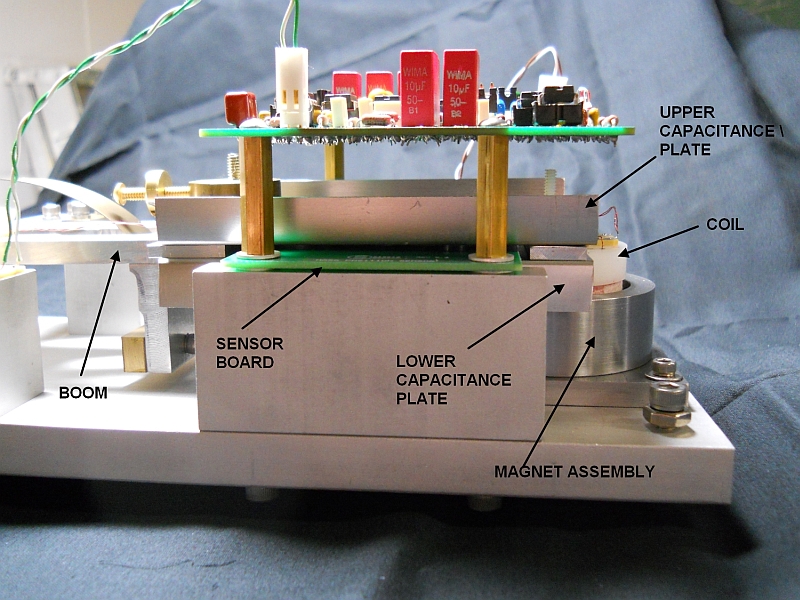
The capacitance plates straddle a fixed copper clad sensor board. Vertical movement creates a change in the capacitance of the upper and lower plates. This difference is processed by the circuitry resulting in a voltage sent to the coil to force the boom to remain centered.
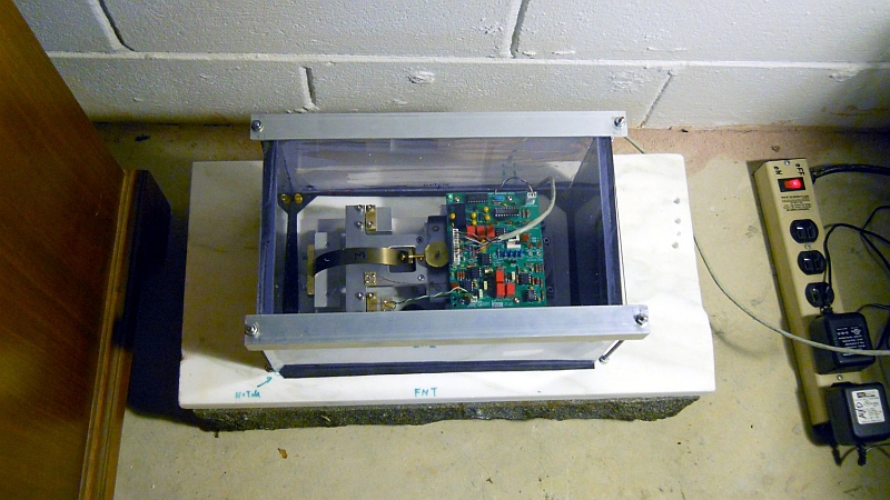
PRESSURE CASE
The circuit board is compact and simple. In operation it senses the capacitance changes occurring with vertical movement. The feedback loop sends a current through the forcing coil that keeps the boom centered with respect to the frame, the feedback current being proportional to ground acceleration.
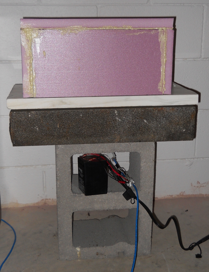
I took a different approach to the pressure case. By leading the cables through the marble slab I was able to make the polycarbonate box without ports. The case is placed on a 1/16th inch butyl gasket and pressed into the slab with angle aluminum and corner threaded rods.
Plinth - Marble is reasonably easy to drill with conventional carbide masonry bits and is almost as rigid as granite. I drilled a ¼ inch hole laterally from the side of the plinth about 3 inches long toward the interior. A shallow ½ inch hole from the top surface exposed the end of the access hole. A cat5e cable nicely fits through the ¼ inch access hole and bends easily up through the ½ inch hole. I made sure the interior end of the cable was long enough to reach the 12-pin Molex connector before sealing up the access hole with expansive foam. I drilled 3/16th inch holes through the plinth at each corner and installed four 8-32 threaded rods at each location. Using aluminum angle I made two brackets that run lengthwise on either side of the case to hold the case against the gasket and plinth.
Case - The case is made of ½ thick polycarbonate glued up from ¼ thick sheets using Weld-On #4 solvent. Pieces were cut to size using a table saw with a carbide-tooth blade run at the highest RPM. I experimented with finishing the edges using a router but discovered the saw and a slow feed gave a good enough finish for solvent gluing. Once the four sides of the case were glued I prepared the bottom edges of the case by puddling solvent in the shape of the case footprint on a glass plate and placing the case on the plate, lifting it slightly a couple times to make sure solvent flowed to all parts of the edges. I left it on the glass overnight to dry and in the morning the bottom edges of the case had molded to the glass and were mirror smooth and flat. I then glued the top to the sides.
Gasket The gasket is cut from a 1/16 inch flat butyl rubber sheet and extends about 1/8 inch on either side of the case footprint.
Update - 11/1/13 - This unit has run trouble-free since May 2012. Other than having to touch-up my solder points a year ago I have had no problems. My original plan to move it to a pier in soil just doesn't seem necessary since I can't access bedrock and performance seems quite good as it is. The Inyo sits on an odd arrangement of rock slabs on the basement floor. The seismometer and pressure case sit on a marble plinth. The plinth is placed on a granite headstone using three points of contact provided by three small jam nuts. The headstone is balanced on a 16 inch cinder block on the basement slab. I constructed this as a temporary expedient when I made adjustments a year ago because I got tired of lying on the floor. But, I can see no evidence of degraded performance and may have benefited by raising the unit above the floor perhaps providing a little more distance from thermal changes and drafts. It is definitely unconventional but other than being more vulnerable to damage during a severe local quake it seems to work.